

I decided to use Voronoi cells to model tectonic plates. Let me clarify that I am generating one Voronoi cell per tectonic plate. I am not using Voronoi cells as polygonal map tiles as Amit Patel did in his polygonal map generator. I am generating a small number of large Voronoi cells as tectonic plates, and eventually I’ll rasterize everything to a high definition boring old square tile map.
What is a Voronoi Diagram?
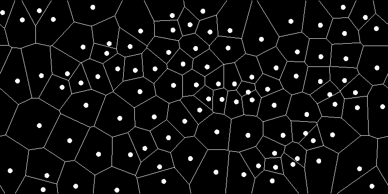
A Voronoi diagram splits divides a space into cells based on a set of points, where each point gets a cell. Each cell consists of all the space closest to the given cell. Although my teachers always said it’s best to explain it in your own words, I’m pretty sure the best way to explain something is with someone else’s picture.

The edges (of the cells) in a Voronoi diagram delineate the “halfway boundaries” between each pair of points. That is, all edges are equidistant from the nearest two cells. Each intersection of edges is equidistant from at least 3 points.
What is a Delaunay Triangulation?

According to Wikipedia: “A Delaunay triangulation … is a triangulation such that no point P is inside the circumcircle of any of any triangle. Delaunay triangulations maximize the minimum angle of all the angles of the triangles in the triangulation; they tend to avoid sliver triangles.”
A triangulation is a graph (a set of points and edges) such that no more edges can be added without crossing existing edges. Basically, a Delaunay triangulation:
- Connects the points in such a way that you get triangles
- Tries to make the triangles as equilateral as possible (avoiding long skinny triangles)
- This involves circumcircles
Why are we even looking at Delaunay triangulations? It turns out that Voronoi diagrams and Delaunay triangulations are dual graphs of each other. That means if you find one, you can easily convert it into the other.
Also, it turns out that while Voronoi diagrams are easier to understand (in my opinion) than Delaunay triangulations, Delaunay triangulations are much more intuitive to code (not my opinion, that’s just true). The algorithm I’m using takes advantage of this fact and generates the Delaunay triangulation, and then flips it into a Voronoi diagram.
Algorithm Overview
The algorithm I am using is:
- Make random points
- Draw a Delaunay triangulation
- Convert the Delaunay triangulation to a Voronoi diagram
- Relax the points and repeat from Step 2 a few times
This algorithm is  where n is the number of points (or cells in the Voronoi diagram).
Aside: For those interested, there is an  algorithm called Fortune’s algorithm which uses a clever sweep-line approach to directly and efficiently generate Voronoi diagrams. I originally tried to implement this version, but it is far more complex and has a greater potential for floating-point arithmetic issues. If I were using Voronoi cells as the tiles for a polygonal tile map, then the algorithmic runtime might be important. However, since I only need at most a few dozen for tectonic plates, the simpler algorithm is fine. My implementation only started slowing down in the thousands of points. It’s important to note that this algorithm still theoretically has floating-point issues if two points are randomly generated extremely close together.
Aside: Also, for those in C++, I believe Boost recently added a comprehensive Voronoi library. If the Delaunay triangulation algorithm suffices, I encourage you to try your own implementation, as it isn’t too difficult or math intensive.
1. Random Point Generation
No tricks here. I pick a range to work in, say x = (0, 800) and y = (0, 400). Then I use a random number generator to pick some random points. We’ll generate 9.

2. Delaunay Triangulation
The Delaunay triangulation algorithm I’m using is called the Bowyer-Watson algorithm. It depends on the following: if I already have a Delaunay triangulation for a given set of points, I can add a new point and update my triangulation. This boils down to 2 steps:
- Remove all triangles invalidated by the new point
- Fill in new triangles until we have a valid Delaunay triangulation again
Adding New Points to the Triangulation
Let’s do an example. Suppose I magically already have the Delaunay triangulation for our 9 points.

Now I add a new point, point 10.

Triangle Invalidation
How do I update my triangulation? Remember that the constraint of the Delaunay triangulation is that: “No point is within the circumcircle of any triangle.” Our new point clearly violates this constraint. Therefore, all I have to do is find all the triangles invalidated by my new point, i.e. all the triangles whose circumcircles my new point resides in. Point 10 invalidates three existing triangles.

Fortunately the circumcircle calculation isn’t too difficult. First I find the center of the circumcircle, which is equidistant from the triangle’s three points (formulas abound online). Then, if the new point is within radius distance from the triangle center, it is in the triangle’s circumcircle, and the triangle is invalidated. The radius is the distance from any of the triangle’s three points to the circumcenter.
What do I do with these invalidated triangles? Remove them. Get them out of here. This leaves behind a polygonal hole, formed by points 1-3-7-8-4-1.

Fixing the Polygonal Hole
Now all I have to do is fill in the polygonal hole with triangles that satisfy the Delaunay triangulation. It turns out this is pretty easy. I just draw lines from the new point to all of the polygon’s corners, like slicing a pie. Why is this guaranteed to generate a Delaunay triangulation? Go check Wikipedia; I hate proofs.

Voila! I have successfully added a new point to an existing Delaunay triangulation and fixed our triangulation. Here are the steps listed:
- Retrieve a new point
- Identify all triangles invalidated by the new point and add them to the list invalidatedTriangles
- Remove all the invalidated triangles from the triangulation.
- Fill the polygon hole with new triangles by slicing it into pie pieces
Those steps are the main muscle of the Delaunay triangulation algorithm. For those of you who care, you may notice step 2 will cause this algorithm to be because for every new point we must check it against every triangle. There is probably a way to use sorting to reduce this to , but later on the conversion to Voronoi will also be so there’s really no point.
The Base Case
I have most of the algorithm, but I started with a Delaunay triangulation. I can add any new point into my triangulation, but at the beginning, when all I have are points, how do I get that initial triangulation? Well, here’s a fun little device.
At the beginning, I’ll just draw a huge triangle around all my points.

Why? If all my points are within my starting triangle, then they are all within its circumcircle, and are all guaranteed to invalidate it when added to the triangulation. After I’ve generated the full Delaunay triangulation, I can either leave the starting triangle in or remove it in some manner. I am going to leave in the starting triangle because it will be useful when we flip to Voronoi.
The easiest way to guarantee the starting triangle is large enough is to give it the vertices { (0,0), (0, 2 * maxY), (2 * maxX, 0) }.
And that’s the full Delaunay triangulation. Leaving the big starting triangle in, I end up with this.

Pseudocode
Here is pseudocode for adding a new point to an existing triangulation. I’m leaving out the base case triangle generation and the main for-loop (Triangulation should be called once for every point).
Triangulation(List triangles, Point newPoint):
    Let List badTriangles, List polygonHole be empty;
    CALL FindInvalidatedTriangles(triangles, newPoint, badTriangles, polygonHole);
    CALL RemoveDuplicateEdgesFromPolygonHole(polygonHole);
    CALL RemoveBadTrianglesFromTriangulation(triangles, badTriangles);
    CALL FillInPolygonHole(triangles, newPoint, polygonHole);

FindInvalidatedTriangles(List triangles, Point newPoint, List badTriangles, List polygonHole):
    FOR each t in triangles:
        IF the circumcircle of t contains newPoint:
            add t to badTriangles;
            add all of t's 3 edges to polygonHole;

RemoveDuplicateEdgesFromPolygonHole(List polygonHole):
    FOR each edge in polygonHole:
        IF the edge's second vertex is left of its first coordinate:
            flip the edge around by swapping its vertices

    sort the edges in polygonHole by first vertex x-coordinate
    FOR each edge in polygonHole:
        IF edge is equivalent to previous edge, remove current edge

RemoveBadTrianglesFromTriangulation(List triangles, List badTriangles):
    FOR each t in badTriangles:
        find t in triangles and remove

FillInPolygonHole(List triangles, Point newPoint, List polygonHole):
    FOR each edge in polygonHole:
        Let v1 and v2 be the two vertices of edge
        Let t be a new triangle with edges {edge, newPoint to v1, newPoint to v2}
        add t to triangles
Additional notes:
- While triangles and badTriangles are lists of triangles, polygonHole is a list of edges
3. Conversion to Voronoi
To convert a Delaunay triangulation to a Voronoi diagram, you must connect the circumcenters of triangles who share an edge. Since the Delaunay triangulation has already done most of the hard work, I’ll start with the pseudocode.
Pseudocode
let points be our list of points;
let triangles be our Delaunay triangulation;
let edges be the distinct edges in triangles;

FOR each edge in edges:
    IF edge has a triangle on both sides:
        let t1, t2 be the triangles adjacent to edge
        let cc1, cc2 be the circumcenters of t1, t2
        let newEdge be the edge (cc1, cc2)
        add newEdge to vorEdges
A few notes:
- edges can be constructed by looping through the triangles, getting all their edges, then removing all duplicate edges.
- The edges in the edge list need pointers to the two triangles adjacent to the edge
- Not shown in the pseudocode: Voronoi edges extending past the boundaries of the space should be clipped to end at the boundaries. Voronoi edges entirely outside the boundaries should be ignored. All the edges involved with the big starting triangle will be at least partially outside the boundaries.


4. Relaxation
I have the Voronoi diagram, but it’s very uneven. Variety is great, but tectonic plates can only be so oblong. I need a way to make the Voronoi cells a bit more regular.
The solution is relaxation. This isn’t referring to R&R but to a class of methods used to make a set of points more evenly spaced out.
Lloyd’s Algorithm
Lloyd’s algorithm moves all points toward the centroid of their Voronoi cells. Conveniently, I already have the Voronoi cells. The centroid of a cell is equal to the average of all the boundary points of the cell, which is also an easy calculation.
Run enough times, Lloyd’s algorithm will perfectly space out the points to make cells as uniform in size and shape as possible (approaching equivalently sized n-sided regular polygons). You can see this effect in the images below, thanks to Dominick Moritz via Wikipedia.


How much the points are relaxed has a large impact on the shape and uniformity of the cells.
Ruppert’s Algorithm
As an alternative, Ruppert’s algorithm is used in computational meshing to ensure triangles in a mesh are “high quality.” High quality basically means closer to equilateral. Importantly, Ruppert’s algorithm operates on a triangulation and returns a Delaunay triangulation.
I didn’t end up using Ruppert’s algorithm because it tended to generate too many small cells.
Repeat
After relaxation, the points have changed, so I go back to Step 2 and regenerate the Delaunay triangulation, then flip to Voronoi.
Cylindricalization
With the normal 2D Voronoi diagram algorithm running, it’s relatively easy to make it work for cylindrical spaces.
What changes are necessary to wrap the map around the left and right boundaries? Somehow, we have the get the points near the left and right boundaries to sense each other. The simplest way to do this is copy all of the points and shift them right by the maximum x-coordinate. Now I have two maps taped together: the “real” map and the duplicated “ghost” map to the right.
Running through the Delaunay triangulation (with the “real” and “ghost” maps combined into a single map), I get a single triangulation with two similar but nonidentical halves. I can wrap my original map into a cylinder by taking all the edges straddling the border between the “real” and “ghost” maps (edges crossing the maximum x-coordinate), disconnecting them from their ghost points to the right, and reconnecting them to the equivalent “real” points near the left boundary. Then I can discard my ghost map section and proceed with the Voronoi flip, carefully dealing with all the edges that cross the boundary.
Final Images and Notes

Final Notes


- Cylindricalization: Note how the left edge of the map and the right edge line up.
- Cylindricalization: I had to limit how much the relaxation step was allowed to relax the y-axis. Because the cylindricality meant the x-axis was infinite but the y-axis was finite, unlimited relaxation herded all my points away from the y-boundaries, forming a band near the middle. That’s why in Cells:20, Relaxations: 50, the Voronoi cells are still not very regular.
- Runtime: The 1000-point 3-relaxation version took about 5 seconds to run. I’m sure this algorithm could be coded more efficiently.
- Moving Forward: I chose 20 Cells, 3 Relaxations as the diagram to continue with. All the pictures on the website use those parameters. It’s a few more than I believe is geologically accurate but it produces pretty good results with my terrain work.
- Bug: There is still a theoretical floating point bug that can occur if two points are generated extremely close together. I should implement a check that checks for, removes, and replaces such points during the random point generation.
- Bug: There is also an issue with the occasional edge near the bottom border not appearing. I believe this is a rendering issue, not an issue with the Voronoi algorithm, but I’ll have to check.
Next Up
Making tectonic plates and deriving continents, oceans, faults, and coasts.